Interactive View Range
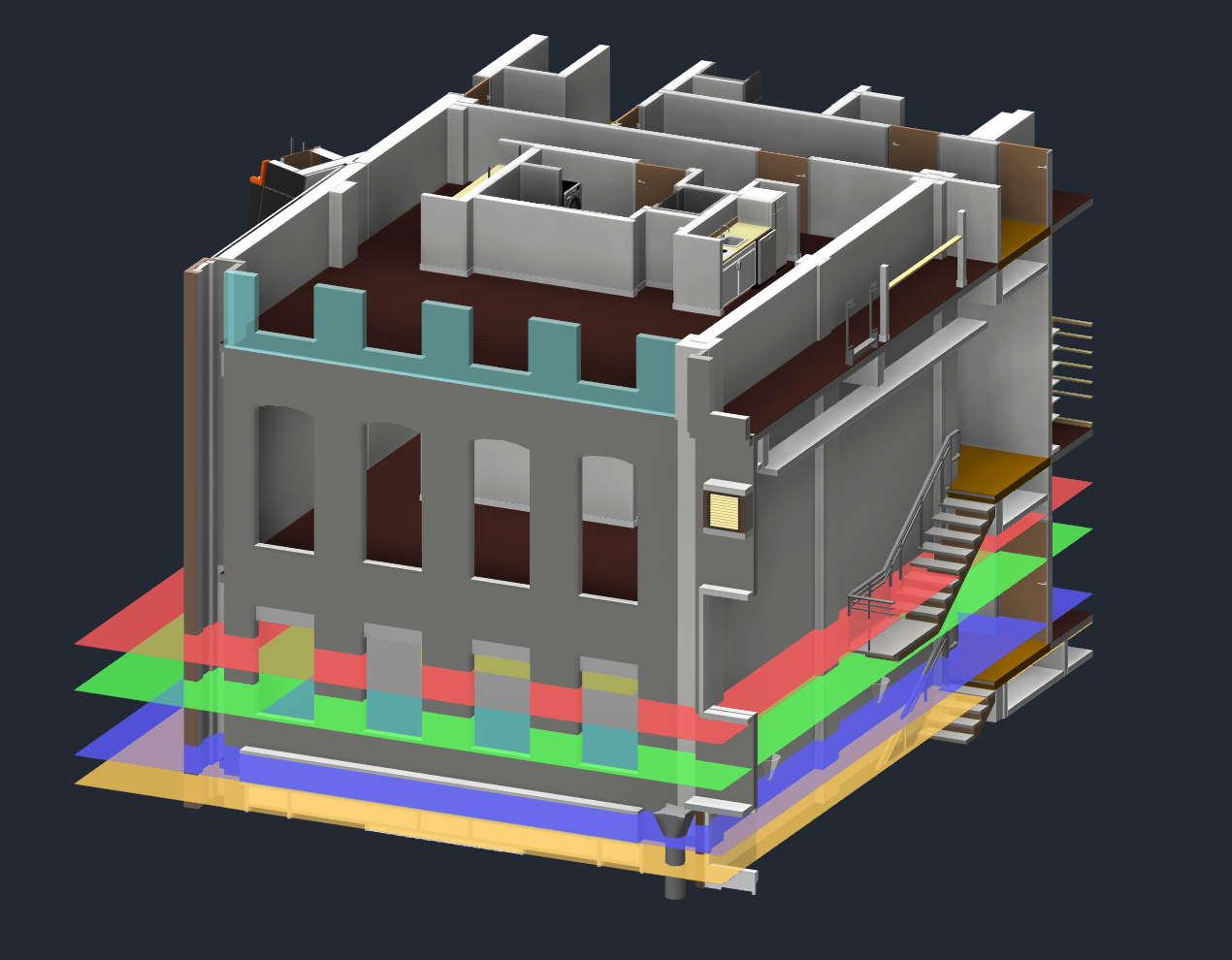
Interactive View Range transforms the abstract concept of plan view ranges into a visual, interactive experience. Instead of entering numbers in a dialog, you see the actual view range boundaries as color-coded planes in 3D and adjust them by simply moving them with Revit’s standard tools.
Getting Started
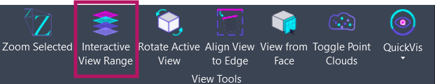
Section titled “Getting Started”Find Interactive View Range on the Amorphous ribbon tab in the View Tools panel.
Features
Section titled “Features”- Color-coded visualization - See all four view range boundaries as transparent colored planes
- Interactive adjustment - Move planes vertically using standard Revit move tools
- Real-time validation - Ensures plane hierarchy is maintained before applying
- Reset capability - Snap all planes back to original positions to start over
- Movement feedback - Detailed summary shows exactly how much each plane moved
- Searchable view selection - Filter plan views by name with real-time search
View Range Planes
Section titled “View Range Planes”The tool creates four transparent planes, each representing a view range boundary:
| Plane | Color | Purpose |
|---|---|---|
| Top Clip | Red | Upper boundary - elements above this are not visible |
| Cut Plane | Green | Elements are shown in section at this height |
| Bottom Clip | Blue | Lower boundary - elements below this are not visible |
| View Depth | Orange | Additional depth for viewing elements below bottom clip |
How to Use
Section titled “How to Use”Basic Workflow
Section titled “Basic Workflow”- Open a 3D view in your project
- Click Interactive View Range on the Amorphous ribbon
- Select a plan view from the dialog that appears - use the search box to filter
- Transparent planes appear in your 3D view at the current view range elevations
- Move the planes vertically using Revit’s Move command to adjust boundaries
- Click APPLY to update the plan view, or CANCEL to discard changes
View Selection Dialog
Section titled “View Selection Dialog”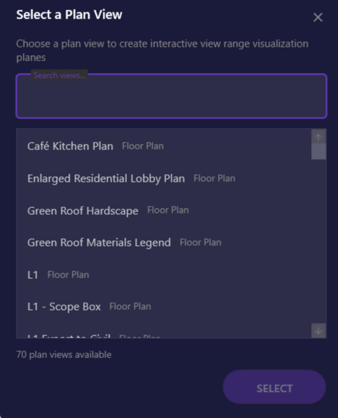
The selection dialog lists all floor plans and structural plans in your project.
| Element | Description |
|---|---|
| Search box | Type to filter views by name in real-time |
| View list | All available floor and structural plans |
| SELECT button | Confirm selection and create visualization |
Keyboard shortcuts:
- Type to search
Enter- Select highlighted view- Double-click - Select and confirm
Control Panel
Section titled “Control Panel”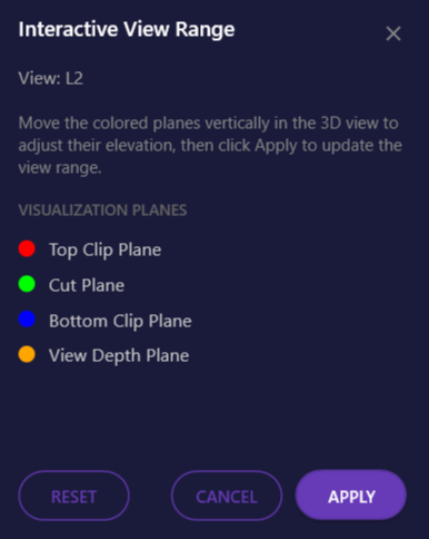
The control panel stays on top while you work, showing the color legend and action buttons.
| Button | Action |
|---|---|
| APPLY | Update the plan view’s view range and remove visualization |
| RESET | Return all planes to their original positions |
| CANCEL | Remove planes without applying changes |
Keyboard shortcuts:
ESC- Cancel and remove planesEnter- Apply changes (when control panel is focused)
Adjusting Planes
Section titled “Adjusting Planes”- Select a plane in the 3D view (click on the colored surface)
- Start the Move command (keyboard shortcut or ribbon)
- Drag vertically to the desired elevation
- The plane snaps to your placement
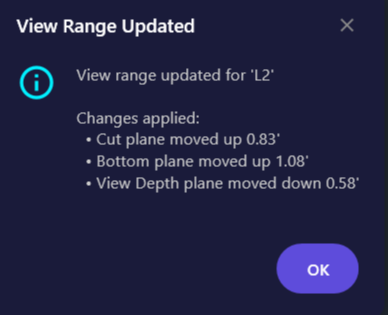
Applying Changes
Section titled “Applying Changes”When you click APPLY, the tool:
- Validates the plane hierarchy (Top >= Cut >= Bottom >= View Depth)
- Calculates the movement for each plane
- Updates the plan view’s view range settings
- Shows a summary of changes made
- Removes the visualization planes
Use Cases
Section titled “Use Cases”Understanding View Range
Section titled “Understanding View Range”Quickly visualize how a plan view’s current settings relate to the 3D model geometry. See exactly where the cut plane intersects walls and where the bottom clip falls relative to floor elements.
Troubleshooting Missing Elements
Section titled “Troubleshooting Missing Elements”If elements aren’t appearing in a plan view, visualize the view range to see if elements are being clipped. Adjust boundaries to include the missing elements.
Coordinating with Levels
Section titled “Coordinating with Levels”See exactly where view boundaries fall relative to floors, ceilings, and other elements. Useful for views that need to capture specific floor-to-floor ranges.
Training New Users
Section titled “Training New Users”The visual representation makes it much easier to explain view range concepts to team members who are new to Revit or unfamiliar with how view ranges work.
- Assign a keyboard shortcut to the command for faster access when working with multiple views
- Use Reset often - If your adjustments get confusing, Reset returns all planes to their starting positions
- Work in perspective 3D - Orbit around to see exactly where planes intersect model geometry
- Isolate relevant elements - Hide or isolate elements in the 3D view to see planes more clearly
Limitations
Section titled “Limitations”- 3D view required - The command only works when a 3D view is active
- Plan views only - Supports floor plans and structural plans; ceiling plans and area plans are not available
- Unlimited ranges - If a view range parameter is set to “Unlimited,” that plane will not be created
- One view at a time - Only one plan view’s range can be visualized at a time
- Plane hierarchy - Top must be at or above Cut, Cut at or above Bottom, Bottom at or above View Depth
Troubleshooting
Section titled “Troubleshooting”All Planes Show as Unlimited
Section titled “All Planes Show as Unlimited”If a plan view has all ranges set to unlimited, the visualization won’t create any planes. Use Revit’s Properties palette to set at least some finite values first.
Cannot See Planes
Section titled “Cannot See Planes”Make sure you are in a 3D view and that model elements are not obscuring the planes. Try isolating or hiding other elements, or orbiting to a different angle.
Planes Disappeared
Section titled “Planes Disappeared”If you closed the control panel without clicking Apply or Cancel, run the command again. It will detect any existing visualization planes and reopen the control panel.
Invalid Plane Order Error
Section titled “Invalid Plane Order Error”If you moved a plane past another (e.g., Cut above Top), click RESET to restore all planes to their original positions, then adjust more carefully.
Related Tools
Section titled “Related Tools”- Rotate Active View - Rotate plan views to any angle
- Zoom to Selected - Navigate views quickly