Section Box by Edge
Section Box by Edge creates section boxes that align to the orientation of a selected element edge rather than being constrained to the project’s X/Y axes. This is ideal for working with rotated structural elements, rotated walls or MEP elements, or any geometry that does not align with the project grid. This tool is also helpful when Smart Section Box does not produce expected results with complex geometry, as it gives you explicit control over the section box orientation.
Getting Started
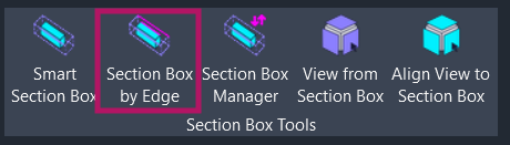
Section titled “Getting Started”Find Section Box by Edge on the Amorphous ribbon tab in the Section Box Tools panel.
The button is enabled when you are in:
- A 3D view (non-template)
- A plan view
- A section or elevation view
Features
Section titled “Features”- Edge-aligned rotation - Creates section boxes rotated to match any selected straight edge
- Automatic structural detection - Beams, columns, braces, and footings get optimal bounding without manual tuning
- Curtain wall support - Choose between isolating a single mullion or the entire curtain wall system
- Multi-view support - Works from 3D views, plan views, sections, and elevations
- Smart view creation - Automatically creates a dedicated 3D view (
SSBox-Edge-{username}) when run from 2D views - Linked element support - Pre-select a link, then pick near any edge inside it with visual feedback
- In-place family support - Handles complex in-place family geometry accurately
How to Use
Section titled “How to Use”Basic Workflow
Section titled “Basic Workflow”- Click “Section Box by Edge” on the ribbon
- Select a non-vertical straight edge on your target element when prompted
- A section box is created aligned to the selected edge, surrounding the element with 2-foot padding on all sides
Angled Structural Framing
Section titled “Angled Structural Framing”For beams, braces, or columns that are not aligned to the project grid:
- Activate the command
- Select a straight edge along the member’s length
- The section box rotates to match the framing orientation
Curtain Walls and Mullions
Section titled “Curtain Walls and Mullions”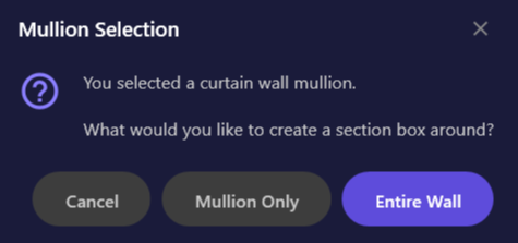
When you select an edge on a mullion, a dialog appears with options:
| Option | Description |
|---|---|
| Mullion Only | Creates a tight section box around just the selected mullion |
| Entire Wall | Creates a section box encompassing the entire curtain wall |
| Cancel | Cancels the operation |
From 2D Views
Section titled “From 2D Views”When you activate the command from a plan, section, or elevation view:
- Click the command while in the 2D view
- Select an edge on any visible element
- The add-in creates a dedicated 3D view named
SSBox-Edge-{username} - The section box appears in the new 3D view, rotated to match your selected edge
Linked Model Elements
Section titled “Linked Model Elements”To create a section box around an element in a linked model:
- Select the Revit Link in the host model (click on the linked model to select it)
- Click “Section Box by Edge” on the ribbon
- Click near a straight edge inside the linked model when prompted
- A magenta flash highlights the detected edge for visual confirmation
- The section box is created in the host model, aligned to the selected edge
User Interface
Section titled “User Interface”Instruction Bar
Section titled “Instruction Bar”
When the command is activated, an instruction bar appears at the top of the Revit window guiding you to select an edge. The bar disappears after you make a selection or press ESC to cancel.
Section Box Result
Section titled “Section Box Result”After selecting an edge, the section box is created with:
| Property | Value |
|---|---|
| Padding | 2 feet on all sides (X, Y, Z) |
| Rotation | Aligned to selected edge direction (projected to XY plane) |
| Center | Calculated from element geometry (volume-weighted for complex shapes) |
Use Cases
Section titled “Use Cases”- Angled structural framing - Isolate beams or braces at non-orthogonal angles
- Rotated columns - View column details when columns are rotated from the project grid
- Curtain wall details - Focus on a specific mullion or an entire curtain wall panel
- Sloped elements - Create aligned views of ramps, sloped slabs, or angled foundations
- Complex in-place geometry - Isolate custom geometry regardless of its orientation
- Ceiling inspection - Create tight section boxes around ceiling elements for coordination
Tips and Best Practices
Section titled “Tips and Best Practices”- Keyboard shortcut: Assign a shortcut via Revit Options > Keyboard Shortcuts for faster access
- Choose visible edges: Select an edge that clearly represents the direction you want the section box aligned to
- Use with Smart Section Box: For multi-element selections or when you do not need specific edge alignment, use Smart Section Box instead
- Save section boxes: After creating an edge-aligned section box, use Section Box Manager to save it for later recall
- 2D view advantage: Picking edges in plan view can be easier than in 3D when elements overlap
Limitations
Section titled “Limitations”| Limitation | Details |
|---|---|
| Straight edges only | Curved edges (arcs, splines) are not supported; select a linear edge |
| Linked element edge detection | Uses nearest-edge calculation; a visual flash confirms the detected edge |
| Vertical edges | Edges that are purely vertical (parallel to Z-axis) default to X-axis alignment |
| Zero-volume geometry | Elements with no solid geometry (symbolic lines, model lines) cannot be processed |
Troubleshooting
Section titled “Troubleshooting””Selected edge is not linear”
Section titled “”Selected edge is not linear””You selected a curved edge (arc or spline). Select a straight edge instead, or use Smart Section Box which works with element bounds rather than specific edges.
”Could not extract any vertices from target elements”
Section titled “”Could not extract any vertices from target elements””This occurs when the element has no solid geometry. Model lines, detail lines, and symbolic elements cannot be used. Select an element with 3D solid geometry instead.
Section box appears but rotation seems wrong
Section titled “Section box appears but rotation seems wrong”The rotation is calculated from the edge direction projected onto the XY plane. For edges that are nearly vertical, the horizontal direction component may be very small, causing unexpected rotation. Try selecting a more horizontal edge.
Edge flash appears but section box rotation seems off
Section titled “Edge flash appears but section box rotation seems off”For linked elements, the section box rotation is calculated from the detected edge direction. If the edge detection picked a different edge than intended (due to picking near a corner), try picking closer to the center of the desired edge. The magenta flash shows exactly which edge was detected.
Related Tools
Section titled “Related Tools”- Smart Section Box - Create section boxes from selected elements (auto-rotation based on element geometry)
- Section Box Manager - Save, recall, and manage section box states across sessions
- View from Section Box - Create 2D views from section box extents
- Align View to Section Box - Orient 3D view to match section box orientation