2D View from Picked Face
2D View from Picked Face streamlines creating views aligned to element faces. Simply pick a face on any element, and the add-in automatically determines whether to create a section or plan view based on the face orientation. It handles linked models, curtain walls, and manages view cleanup so your project stays organized.
Getting Started
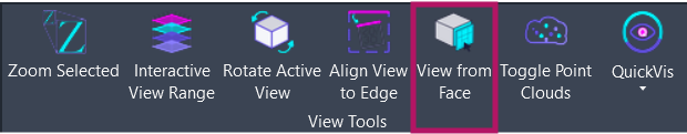
Section titled “Getting Started”Find View from Face on the Amorphous ribbon tab in the View Tools panel.
The button is enabled when:
- A document is open
- The document has an active view
Features
Section titled “Features”- Automatic view type selection - Creates section views for vertical faces, plan views for horizontal faces
- Automatic work plane - Sets the work plane to the picked face, ready for sketching or placement
- Linked model support - Pick faces from linked Revit models with automatic coordinate transformation
- Curtain wall handling - Special options for curtain wall panels and mullions
- Auto-cropping - View crop box automatically sized to the element’s bounding box
- View cleanup - Maintains only the 3 most recent auto-generated views per user
- Smart naming - Views named with username, source info, and timestamp
- Configurable section depth - Adjustable near/far depth settings via Preferences
How to Use
Section titled “How to Use”Basic Workflow
Section titled “Basic Workflow”- Click “View from Face” on the ribbon
- An instruction bar appears: “Select a planar face to create a view”
- Pick a face on any model element
- The add-in automatically:
- Determines the appropriate view type (section or plan)
- Creates the view with proper cropping
- Opens the new view
Linked Model Workflow
Section titled “Linked Model Workflow”To create views from linked model elements:
- Select the Revit Link instance first (click on the link in your view)
- Click “View from Face”
- The instruction bar indicates “Select a planar face from the linked model”
- Pick a face within the linked model
- A view is created in your host model with coordinates properly transformed
Curtain Wall Workflow
Section titled “Curtain Wall Workflow”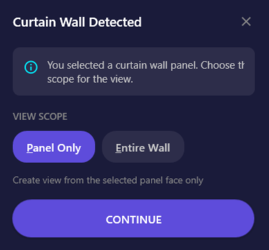
The add-in includes special handling for curtain walls:
When you pick a mullion:
- Automatically uses the entire parent curtain wall
When you pick a panel: A dialog appears with two options:
| Option | Shortcut | Description |
|---|---|---|
| Panel Only | P | Creates view from just the selected panel face |
| Entire Wall | E | Creates view aligned to the full curtain wall location line |
Nearly Horizontal Face Workflow
Section titled “Nearly Horizontal Face Workflow”
When the selected face is tilted between 0-5 degrees from horizontal, a dialog appears asking you to choose:
| Option | Shortcut | Description |
|---|---|---|
| Plan View | P | Creates a floor plan at the face elevation |
| Section View | S | Creates a section aligned to the face |
The dialog displays the exact tilt angle to help you decide.
User Interface
Section titled “User Interface”Instruction Bar
Section titled “Instruction Bar”When the command starts, an instruction bar appears at the top of the Revit window guiding you through the selection:
- Host model: “Select a planar face to create a view”
- Linked model: “Select a planar face from the linked model”
Press ESC at any time to cancel the operation.
View Type Dialog
Section titled “View Type Dialog”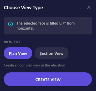
Appears when you pick a nearly horizontal face (within 5 degrees of horizontal).
| Element | Description |
|---|---|
| Info panel | Displays the exact tilt angle of the selected face |
| Plan View chip | Select to create a floor plan (P key) |
| Section View chip | Select to create a section view (S key) |
| Create View button | Confirms selection and creates the view |
| Close button | Cancels the operation |
Curtain Wall Dialog
Section titled “Curtain Wall Dialog”
Appears when you pick a curtain wall panel.
| Element | Description |
|---|---|
| Info panel | Explains the curtain wall was detected |
| Panel Only chip | Use only the panel face (P key) |
| Entire Wall chip | Use the full curtain wall (E key) |
| Continue button | Proceeds with the selected option |
Options & Settings
Section titled “Options & Settings”Preferences
Section titled “Preferences”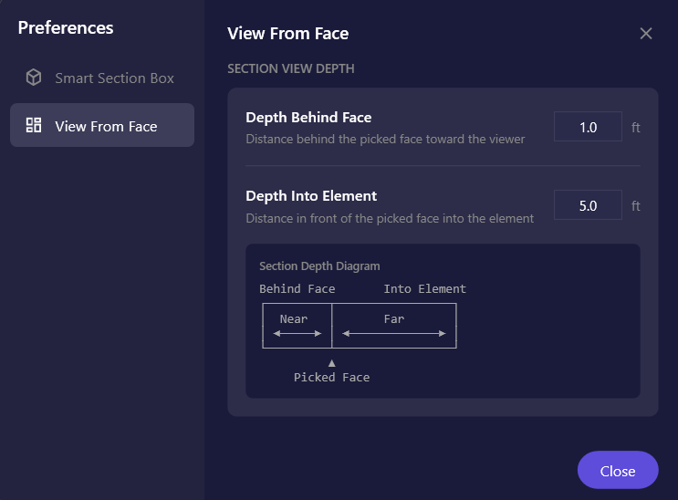
Access preferences via Settings dropdown > Preferences > View From Face.
| Setting | Description | Default | Range |
|---|---|---|---|
| Depth Behind Face | Distance behind the picked face toward the viewer | 1.0 ft | 0 - 50 ft |
| Depth Into Element | Distance in front of the picked face into the element | 5.0 ft | 0.1 - 100 ft |
The preferences page includes a visual diagram showing how these settings affect section view depth.
Automatic View Settings
Section titled “Automatic View Settings”The following settings are applied automatically to created views:
| Property | Value |
|---|---|
| View Scale | 1/8” = 1’-0” (Scale 96) |
| Detail Level | Fine |
| Crop Box | Active and visible |
View Naming Convention
Section titled “View Naming Convention”Views are named automatically using this pattern:
| View Type | Pattern |
|---|---|
| Section (host model) | {username}_AutoFaceView_{YYYYMMDD_HHMMSS} |
| Section (linked model) | {username}_AutoFaceView_{linkname}_{YYYYMMDD_HHMMSS} |
| Plan (host model) | {username}_AutoFacePlan_{YYYYMMDD_HHMMSS} |
| Plan (linked model) | {username}_AutoFacePlan_{linkname}_{YYYYMMDD_HHMMSS} |
Tips & Best Practices
Section titled “Tips & Best Practices”- Keyboard shortcuts: Use
PandSkeys in dialogs for quick selection without clicking - Linked model selection: Always select the link instance first before clicking the button
- Protect important views: Rename views you want to keep. Only views matching the auto-generated naming pattern are cleaned up
- Facade studies: Pick wall faces to quickly create elevation-style views of building facades
- Coordination views: Create views from linked model elements for clash resolution
- Slab analysis: Pick floor slab faces to create plan views at exact slab elevations
Limitations
Section titled “Limitations”| Limitation | Details |
|---|---|
| Planar faces only | Curved surfaces are not supported |
| Single face selection | Only one face can be selected per command |
| Template Assigment | View template assigment is not currenly supported. |
| Project must have levels | Plan views require at least one level in the project |
| ViewFamilyTypes required | Both Section and Floor Plan ViewFamilyTypes must exist |
Troubleshooting
Section titled “Troubleshooting””The selected face is not planar”
Section titled “”The selected face is not planar””This error appears when you click on a curved surface (like a cylindrical column or curved wall). The add-in only supports flat, planar faces. Try picking a different face on the element that is flat.
”Could not retrieve the selected element from the link”
Section titled “”Could not retrieve the selected element from the link””The linked model may not be fully loaded, or the link file may have been modified since it was loaded. Try reloading the link and attempting the selection again.
”No valid Floor Plan/Section ViewFamilyType found”
Section titled “”No valid Floor Plan/Section ViewFamilyType found””Your project is missing the required view family types. This can happen with heavily customized templates. Create at least one floor plan and one section view manually to establish the view family types.
View doesn’t show expected detail
Section titled “View doesn’t show expected detail”If the view appears with less detail than expected:
- Verify the Detail Level is set to Fine in the view properties
- Increase the “Depth Into Element” setting in Preferences
Plan view range doesn’t capture the element
Section titled “Plan view range doesn’t capture the element”The view range is set relative to the nearest level. If your element is far from any level, you may need to manually adjust the view range after creation:
- Open View Properties
- Click “Edit…” next to View Range
- Adjust Top, Cut Plane, and Bottom offsets as needed
Or use Interactive View Range to visually adjust the range with real-time feedback.
Related Tools
Section titled “Related Tools”- Smart Section Box - Create section boxes around selected elements
- Section Box by Edge - Create section boxes aligned to a picked edge
- View from Section Box - Create 2D views from section box extents
- Align View to Edge - Align any view to a picked edge